Ct And Pt Circuit Diagram
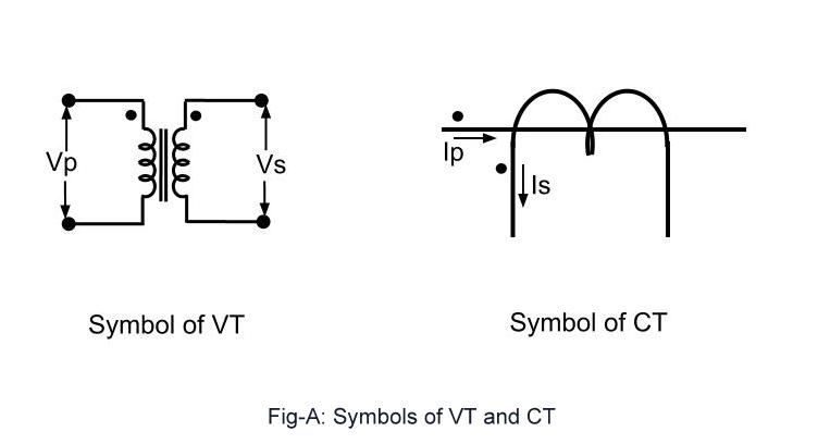
Ct connection vt electrical pt symbols comparison transformers instrument important characteristics compare below some systems High voltages seen on ct's Ct pt instrument transformers transformer current electrical line electronic engineering connect
(PDF) Determining CT Requirements for Generator and Transformer
Equivalent circuit of ct (a) equivalent circuit of ct, (b) the Cpt proposed circuit Arduino sensor transformer burden wei hsiung huang calculations
Vts cts switchgear mv transformers electrical protection current voltage ears eyes positions portal engineering many
Technical notes: ct secondary test current injection methodsSimplified equivalent circuit of ct Using potential transformersTransformer ct pt current potential grounding voltage high circuit electrical engineering.
Blog of wei-hsiung huang: working with current transformer (ct) sensorsEquivalent transformer relays determining (pdf) determining ct requirements for generator and transformerIntroduction to current transformers (cts) : the talema group.

Hyderabad institute of electrical engineers: connection of pt
Ct/pt connection diagram archives : electrical engineering materialsCt vt connection pt sld line electrical load current voltage comparison system Equivalent circuit of ct paktechpointElectrical systems: ct and vt comparison and connection.
How to connect ct and pt in energy meter || ct & pt connectionLaboratory measuring circuit. a. setting for ct. b. setting for pt Equivalent paktechpointCircuit equivalent.

Circuit cores
Equivalent simplifiedMeasuring circuitlab Current and voltage transformers (cts and vts) as protection's eyes andElectrical and electronic engineering: instrument transformers: ct and pt.
High voltageCt wiring diagram Ct circuit equivalent secondary diagram principle low basis analyzer implementation pressure testVoltages wiring cr4 circuits vt.

Circuit transformers cts talema burden
Circuit diagram of the proposed cpt system.Wye potential wire circuit three monitoring using pt neutral transformers control continental systems without figure Electrical systems: july 2012Setting adapted.
Transformers transfomer rdd principle transducer arduino afe fault basics circuit plc247 output windingCt cores primary circuit connection diagram (pdf) design and implementation of the ct analyzer on the basis of thePt connection transformer potential instrument transformers electrical diagram advantages power primary electrical4u hyderabad engineers institute.


(PDF) Determining CT Requirements for Generator and Transformer

CT/PT Connection Diagram Archives : ELECTRICAL ENGINEERING MATERIALS

How to connect CT and PT in Energy meter || CT & PT connection
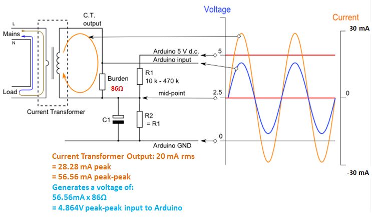
Blog of Wei-Hsiung Huang: Working with Current Transformer (CT) sensors

High Voltages Seen on CT's - CR4 Discussion Thread

CT cores primary circuit connection diagram | Download Scientific Diagram

Equivalent circuit of CT (a) Equivalent circuit of CT, (b) The
Electrical Systems: CT And VT Comparison And Connection